PRODUCTS
CONTACT US
SHENLU HYDRAULIC
Tel: +86-0510-83050688
Tel: +86-0510-83959581
E-mail: sales@shenlu.net.cn

Rolling machine
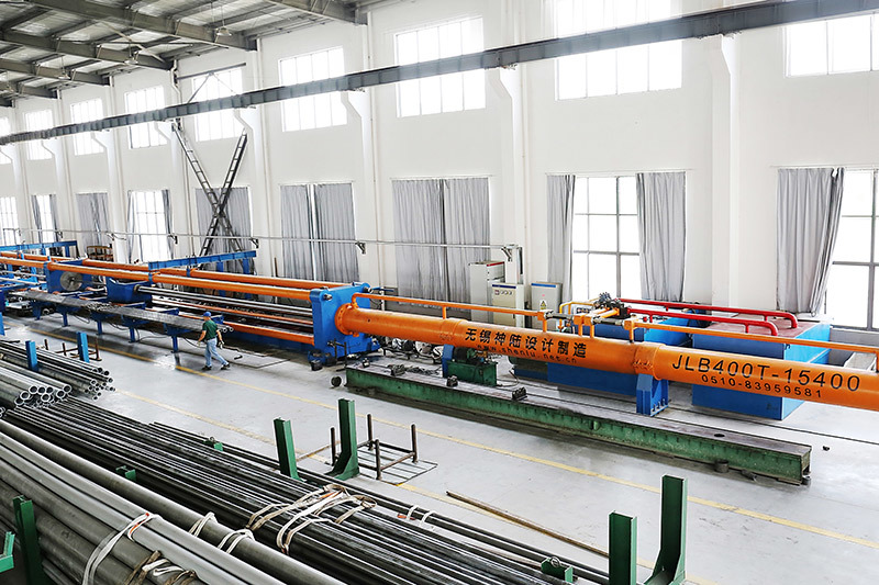
The precision hydraulic cold drawing machine first inserts a core rod into the inner hole of the pipe when drawing steel pipes. Then, the core body is placed, and the front end of the steel pipe that has been threaded onto the core is pushed out of the extraction block. The pre-tightening oil cylinder is started to clamp the steel pipe, and the vehicle is pulled to the starting position. The main oil cylinder begins to draw out. At the same time, the gas cylinder is pulled out, the end of the steel pipe is released, and the finished pipe is pulled out from the valve body. The slider moves in the opposite direction, allowing the plug to be quickly extracted from the pipe, facilitating smooth punching. When using the cold drawing machine to draw steel pipes, the core rod is first placed into the inner hole of the pipe, then the core rod head is installed, and the front end of the steel pipe that has been placed on the core rod head is pushed out to the drawing die seat. The pre-tightening cylinder is started, clamping the steel pipe with the plate teeth, and the traction vehicle is in the starting position, while the main cylinder begins to pull. At the end of the drawing process, the pre-tightening cylinder moves, releasing the steel pipe fork from the plate teeth, pushing the finished pipe out of the vehicle body, and the slider moves in the opposite direction, allowing the plug to quickly exit the pipe, ensuring smooth discharge. In the 1990s, with the continuous in-depth research and application of cold drawn steel pipe technology in China, cold drawn steel pipe technology has been widely applied in the manufacturing of hydraulic cylinders and oil cylinders for engineering machinery. The cold drawing machine is the main processing equipment for cold drawn steel pipes, used for the cold drawing of black and non-ferrous metal bars at room temperature, as well as the secondary processing of waste steel pipes after hot rolling and extrusion. It is used to produce small diameter pipes, serving as the main processing equipment for precision, thin-walled, and high mechanical performance pipes.
Description
Product Parameters
|
Model
|
JLB150T
|
JLB250T
|
JLB300T
|
JLB400T
|
JLB600T
|
JLB1000T
|
|
|
Maximum Pulling Force (KN) |
1630
|
2700
|
3200
|
4100
|
6500
|
12000
|
|
|
Drawing Speed (M/min) |
0-5.5
|
0-4.5
|
0-4.5
|
0-4
|
0-3
|
0-3
|
|
|
Effective Length of Finished Pipe (M) |
1.5-10
|
1.5-10
|
1.5-10
|
1.5-10
|
1.5-10
|
1.5-10
|
|
|
Thickness of Finished Pipe (mm) |
20
|
25
|
30
|
33
|
42
|
70
|
|
|
Main Oil Cylinder (mm) |
Φ320/Φ 150x10000
|
Φ420/Φ 210x10000
|
Φ450/Φ 210x10000
|
Φ500/Φ 220x10000
|
Φ630/Φ 280x10000
|
Φ850/Φ 350x10000
|
|
|
Number of System Stations (Station) |
2
|
2
|
2
|
2
|
2
|
2
|
|
|
System Working Pressure (Mpa) |
26
|
26
|
26
|
26
|
26
|
26
|
|
|
Maximum System Pressure (Mpa) |
31.5
|
31.5
|
31.5
|
31.5
|
31.5
|
31.5
|
|
|
Pump (Manual Variable Piston Pump) |
160Lx3
|
160Lx2 250Lx1
|
250Lx3
|
250Lx3
|
250Lx3
|
400Lx3
|
|
|
Main Motor (KW) |
55x3
|
55x2 75x3
|
75x3
|
75x2 90x1
|
90x3
|
132x3
|
|
|
Dimensions (WxHxL)
|
1.6x1.4x42
|
1.7x1.5x44
|
1.7x1.5x44
|
1.9x1.8x45
|
2.1x2x45
|
2.65x2.65x60
|
|
|
Weight (T) |
86
|
100
|
120
|
180
|
220
|
300
|
|
Keyword:
Get A Quote
Note: Please leave your email address, our professionals will contact you as soon as possible!
Related Products


